Unbranded
4X4X4 RGB 3D 5mm Multicolour Led Infrared Remote Control Light Cube Kit + Case
4X4X4 RGB 3D 5mm Multicolour Led Infrared Remote Control Light Cube Kit + Case
Couldn't load pickup availability
Brand: Unbranded
Type: 4x4x4 RGB 3D Led Cube
Manufacturer Warranty: 6 Months
UPC: Does not apply
MPN: Does not apply
Year Manufactured: 2022
Features: 4x4x4 3D RGB 2 Pin Cube
Country/Region of Manufacture: China
Smart Home Protocol: Infrared
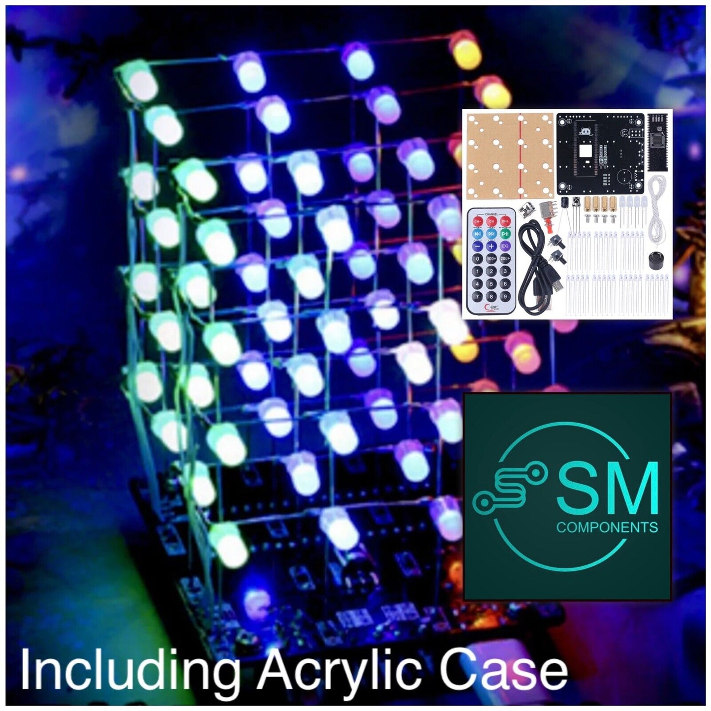
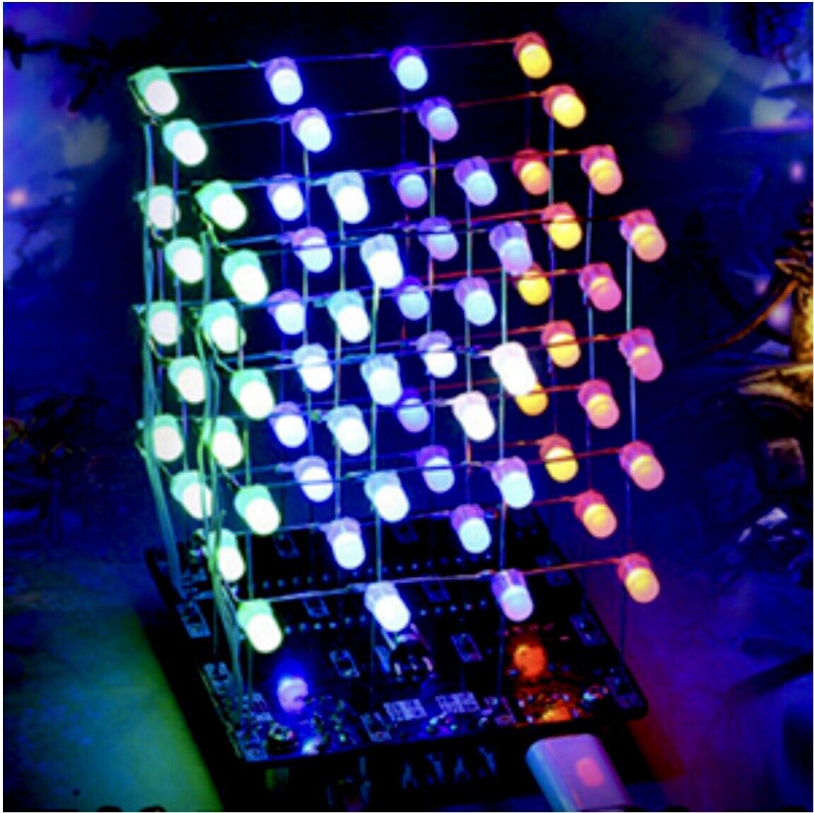
4X4X4 RGB 3D Multicolour Led Remote Control LED Light Cube Including Acrylic Case.
4 X 4 X 4 3D Multicolor Led Light Cube Kit Infrared Remote Control LED Light Cube For Children Kids Toys Gift. Sent with Parcel Post with Tracking.
Please note some photos show 3mm leds, this is a 5mm led kit
Features:
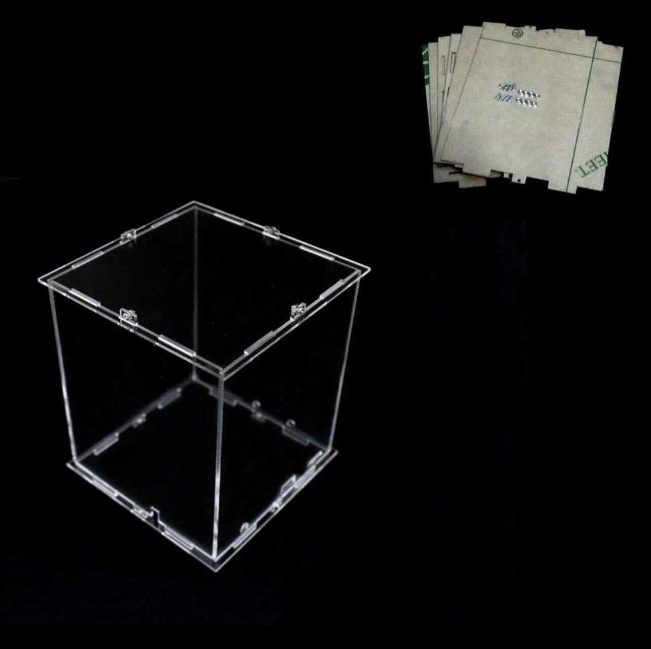
.High Quality:2mm acrylic case.
.Made of 5mm diffused RGB 2 pin LED diodes.
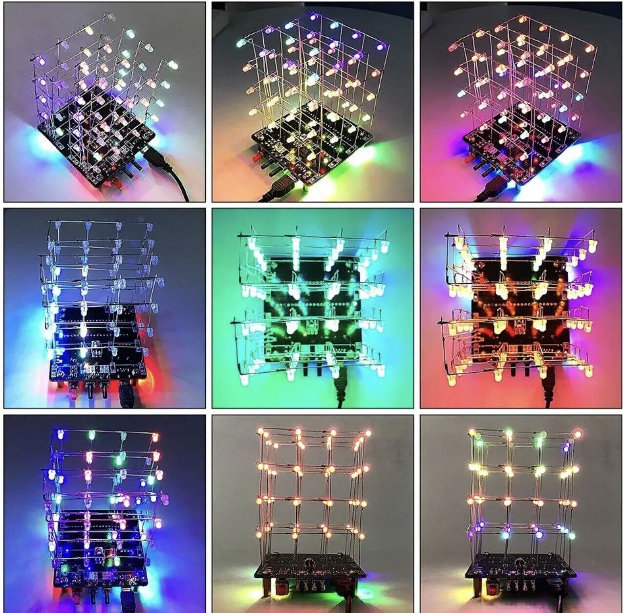
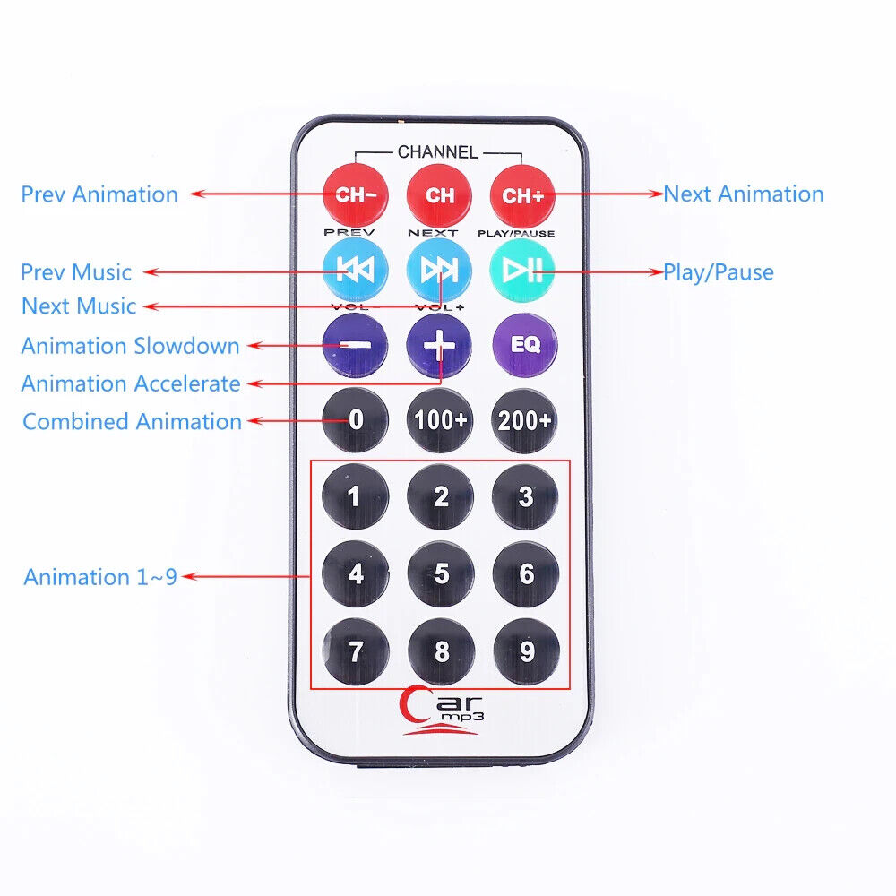
.Full-featured: including animation mode (1 button), music spectrum mode (2 buttons), night light mode (3 buttons).
.High-efficiency and stable infrared remote control in the range of 0-10m
.Power: 5VDC 3A
.Size: 100mm*100mm*120mm
.Control Method: infrared remote control
Use. Electronics collection, decoration, has a certain collection value, keep you sane from lockdowns.
**********THIS KIT DOES HAVE INSTRUCTIONS BELOW ************
Suitable for 14 years old or older.
THIS IS A KIT, YOU MUST HAVE COMMON KNOWLEDGE IN ELECTRONICS AND GOOD FABRICATION SKILLS.
Specifications:
.Color: As Shown
.Material: Acrylic + LED
.Product Dimensions: 10 x 10 x 12cm
.Product Weight: 850g
.Package Dimensions: 20 x 20 x 20cm
.Package Weight: 900g
Installation Steps(Please be patient install! !)
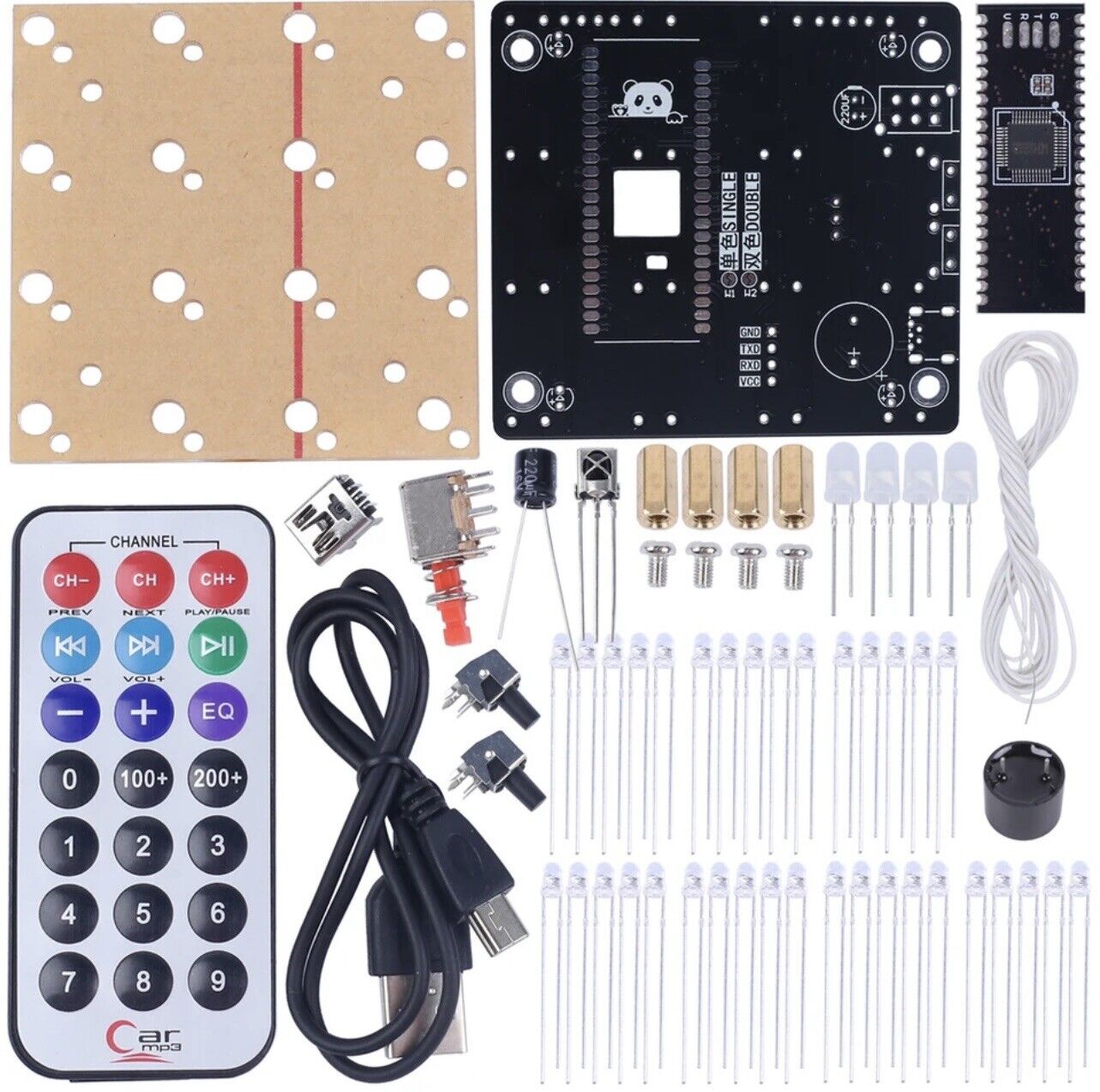
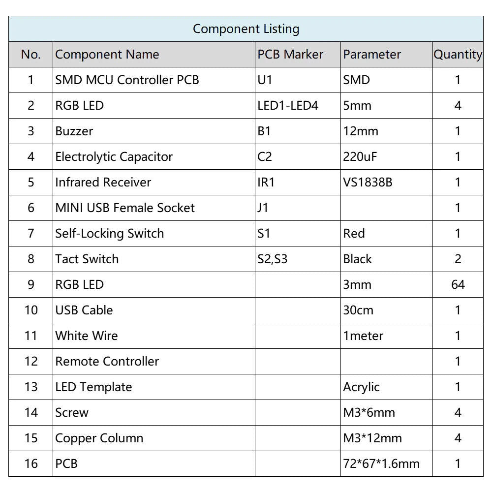
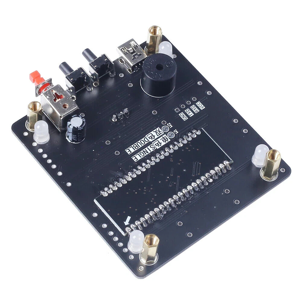
Step 1: Installing the PCB control board.Install 1pcs MINI USB.Note: the pin pitch is small, do not short circuit!And pay attention to the component mounting surface on PCB and do not install components in reverse on PCB side.
Step 2: Install 4pcs 5mm RGB LED at four corners.Note: Distinguish between the positive and negative of the LED. Long pin is positive.
Step 3: Install 1pcs DIP-40 IC socket.Pay attention to its install direction.
Step 4: Install 2pcs Tact Switch black button.
Step 5: Install 1pcs Self-Locking Switch red button.
Step 6: Install 1pcs 220uf Electrolytic Capacitor.Note: Distinguish between the positive and negative. Long pin is positive.
Step 7: Install 1pcs buzzer.Note: Distinguish between the positive and negative. There is a mark ‘+’ on PCB and buzzer.
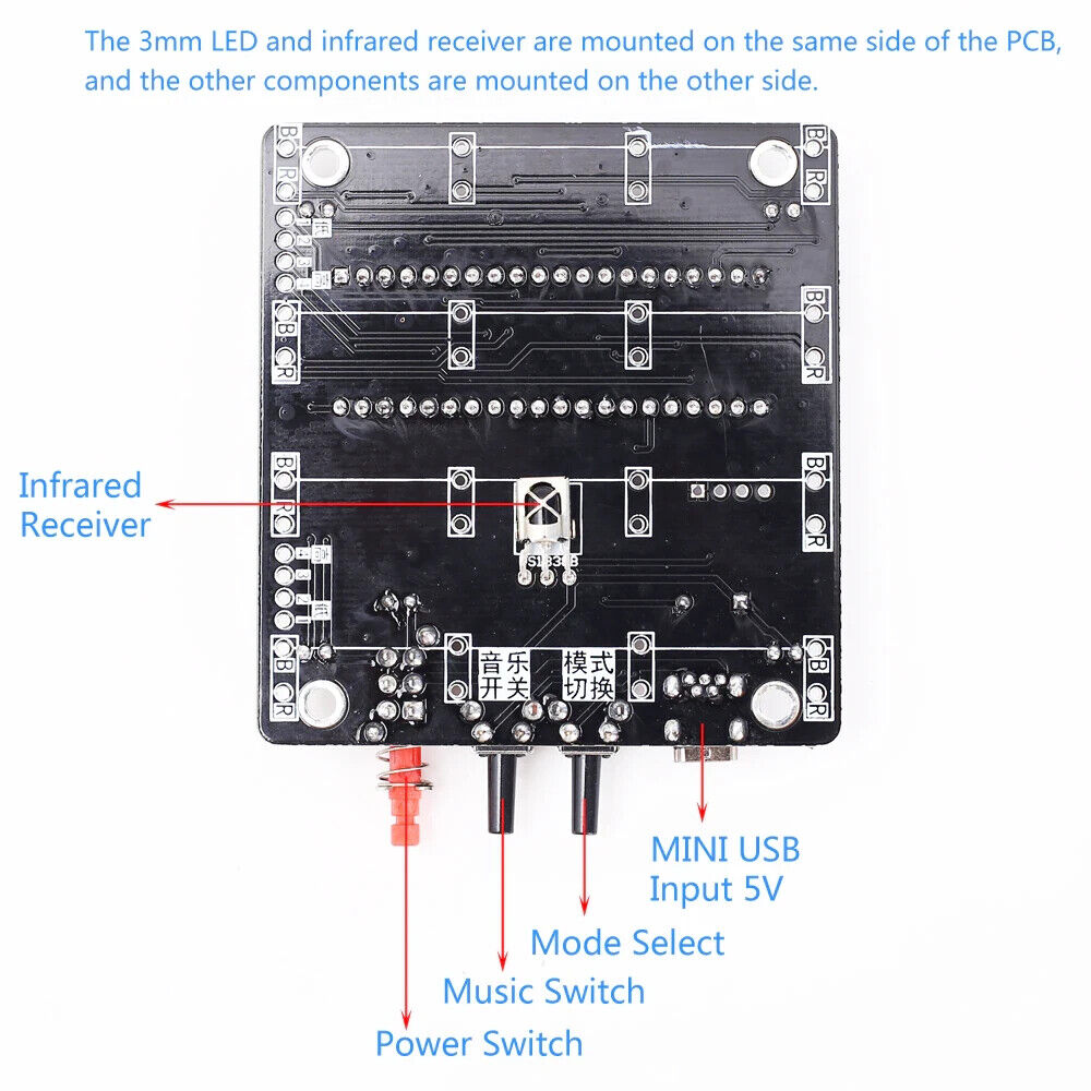
Step 8: Install 1pcs VS1838B Infrared Receiver on another side of PCB.Please do not install it on the same side as other components.
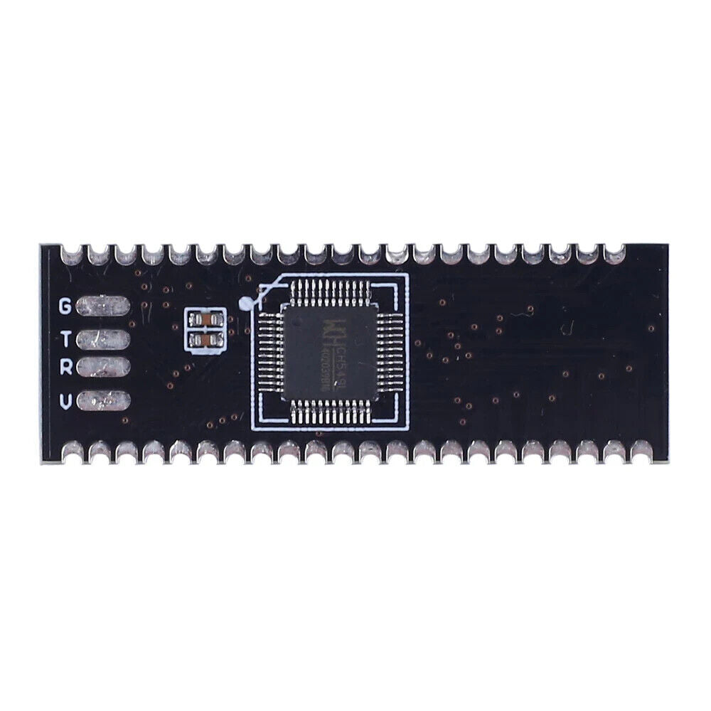
Step 9: Install 1pcs MCU .Pay attention to its install direction.
Step 10: Test.Connect work voltage by USB cable and MINI USB socket.Then turn ON red power supply switch.
10.1>.Power ON is normal and the MCU is normal if 4pcs LED flashing at four corners.
10.2>.Buzzer and left black button is normal if buzzer playing music when press left black button.
10.3>.Right black button is normal if play music changes when press right black button.
10.4>.Remote control and Infrared Receiver are normal if play music changes when press NEXT button.
10.5>.Fault and solution:
10.5.1>.Music is normal but LED can not turn ON means LED installation error.
10.5.2>.LED is normal but music can not play means Buzzer or IC socket installation error.Or user needs to press the left black button multiple times.
10.5.3>.LED can not turn ON or weak light and music can not play means MCU installation error.
Step 11: Learn about LED installation acrylic templates. The biggest hole is used to install 5mm LED and the smaller hole is used to install 3mm LED. This kit uses 5mm LED.
Step 12: Install Bracket for acrylic templates by 4pcs M3*6mm Screw and 4pcs M3*12mm Copper Column.
Step 13: Processing LED pin. 90°bent short pin and the 90°bend long pin.But they bend in different directions and positions.
Step 14: Place LED on acrylic templates.The short pins of the LED are connected to each other and the long pins are connected to each other.
Step 15: Place 4*4 LED on acrylic templates.Make sure that the positive and negative of LED must not be wrong.
Step 16: Fixed all pins.All LEDs are aligned, pay attention to beauty.
Step 17: Test LED by multimeter to make sure every LED can turn ON.If there is an LED that is not lit, please update the replacement LED.
Step 18: Install and test other 3pcs 4*4 LED dot matrix in the same method.
Step 19: Install Bracket by 4pcs M3*6mm Screw and 4pcs M3*12mm Copper Column which form acrylic templates.
Step 20: Bend the negative pole of a 1pcs 4*4 LED dot matrix and bend it 90° inward.Note: Do not short circuit to other pins.And do not damage the solder joint when bending.
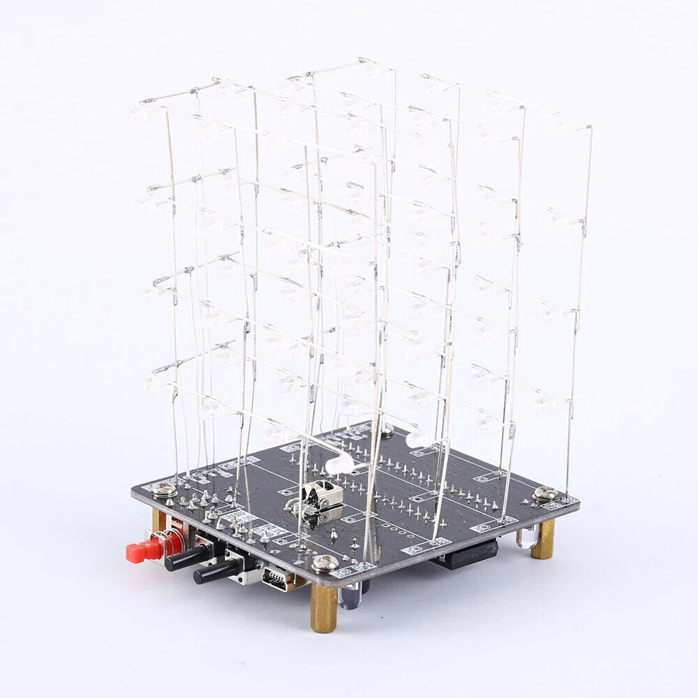
Step 21: Mount the long pins(positive) of the 4*4 LED on the PCB where marked ‘B’. LED head facing to the button.Pay attention to keep the height of the LED consistent and do not tilt.
Step 22: Install 1pcs 4*4 LED dot matrix next to the previous ones.But this 4*4 LED dot matrix no need Bend the negative pins.Pay attention to keep the height of the LED consistent and do not tilt.
Step 23: Connect and fixed negative pins from 2pcs 4*4 LED dot matrix.Cut off the extra pins.
Step 24: Connect each layer by white cable on mark 1~4.The bottom is the first layer.First fixed connection point on ring.Then confirm the length of the wire, then cut the wire.Finally fixed on the PCB.
Step 25:Fixed connect wire for each layer.
Step 26: Bend the negative pole of a 1pcs 4*4 LED dot matrix and bend it 90° inward.Note: Do not short circuit to other pins.And do not damage the solder joint when bending as same to Step 20.Install it next to the previous ones.Pay attention to keep the height of the LED consistent and do not tilt.
Step 27: Install 1pcs 4*4 LED dot matrix next to the previous ones.But this 4*4 LED dot matrix no need Bend the negative pins.Pay attention to keep the height of the LED consistent and do not tilt as same to Step 22.
Step 28: Connect and fixed negative pins from 2pcs 4*4 LED dot matrix.Cut off the extra pins as same to Step 23 and cut off the extra pins.
Step 29: Connect each layer by white cable on mark 1~4.The bottom is the first layer.First fixed connection point on ring.Then confirm the length of the wire, then cut the wire.Finally fixed on the PCB as same to Step 24.
Step 30: Test and finish installation and enjoy.
Shipping & Returns
Shipping & Returns